This will show you how to wire some LEDs to add some light to your rig.
In this tutorial, I show how to create a light string with two bright red LEDs. These are going to be wired to a plug that you can connect to your receiver to power them up.
The plan is to end up with a servo plug going to a length of wire to an LED, then another length of wire to the other LED. These could be installed as a pair of brake or tail lights, or use white LEDs and you could have a set of headlights.
For some, this is fundamental stuff. For others, I hope this helps answer some questions and encourages you to build your own set of lights!
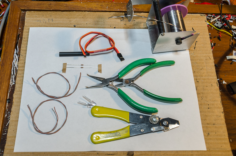
An overall view of the materials to be used.
Side cutters, needle nose pliers and wire strippers.
Two lengths of stranded wire (I think it is 22 gauge) that I recycled from an old network cable.
Two LEDs
Two 150 ohm or 220 ohm resistors
Some heat shrink
A servo cable cut from an old servo
The LEDs need a resistor to limit the current flow or you risk burning them out or limiting their life. The two resistors shown here are 150 ohm (colour code: Black, Green, Brown, Gold).
LEDs are polarity-sensitive devices. This means they will only pass current flow in one direction. The LEDs have a few ways of telling you the polarity of their leads. There will be one lead shorter than the other, and that one is negative. Often there will be a flattened area near the leads and that also indicates the negative lead. I have clipped the negative lead of the upper LED and one end of each resistor.
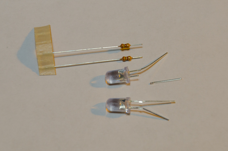
Here you can see that the upper LED has been soldered to one of the resistors. To do this, I first tinned the areas I wanted to solder and then held them together and added a little heat until the tinned bits flowed together.
If you are wondering if these parts are heat-sensitive, the answer is yes. The resistors can tolerate the heat well, but be quick on the LED. A good idea is to hold the LEDs lead with needle nose pliers right close to the LED body. This will help keep the heat from passing into the LED.
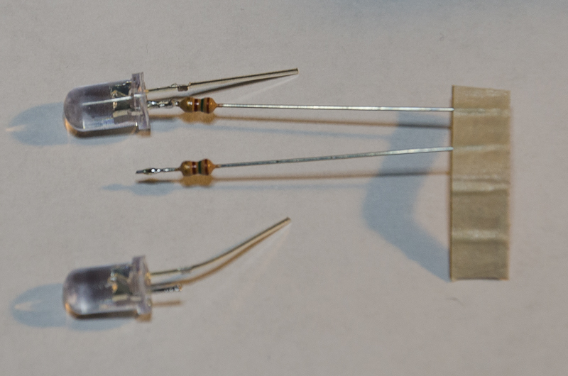
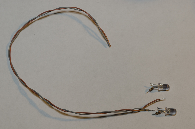
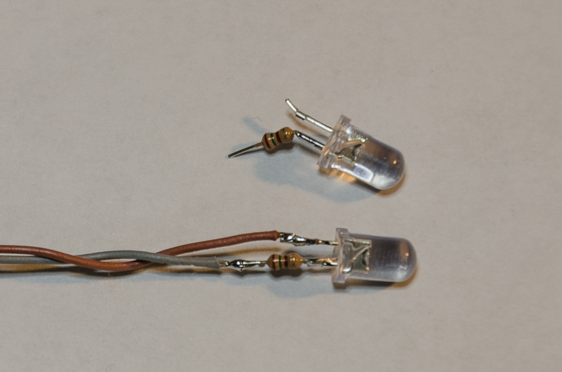
Both LEDs with a resistor soldered to their negative leads. The resistor is bent out like that to stop it from rolling over before I took the photo.
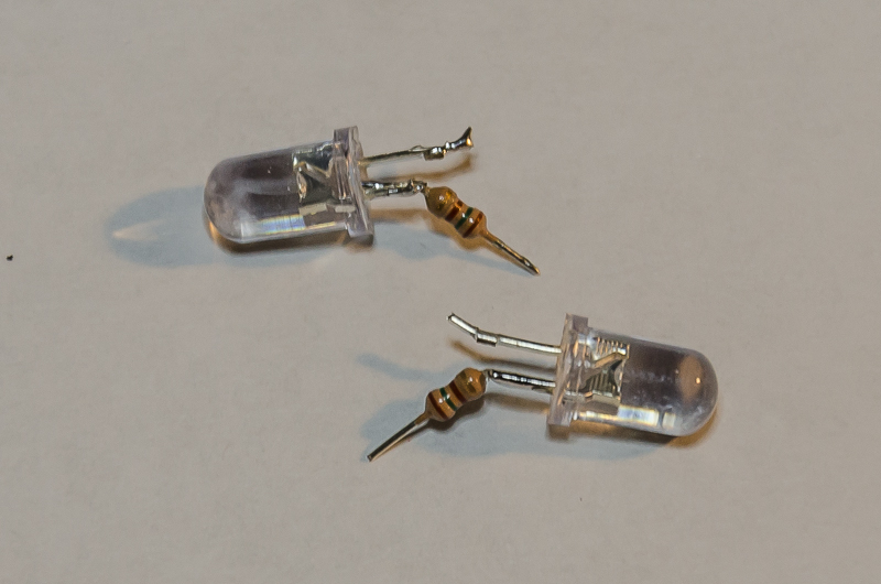
Prepping the wire for soldering... I've decided that the grey will be negative and the brown will be positive. The wire length has been cut and the insulation has been stripped to match the components to be soldered. Again, tin the wires before soldering to make things easier.
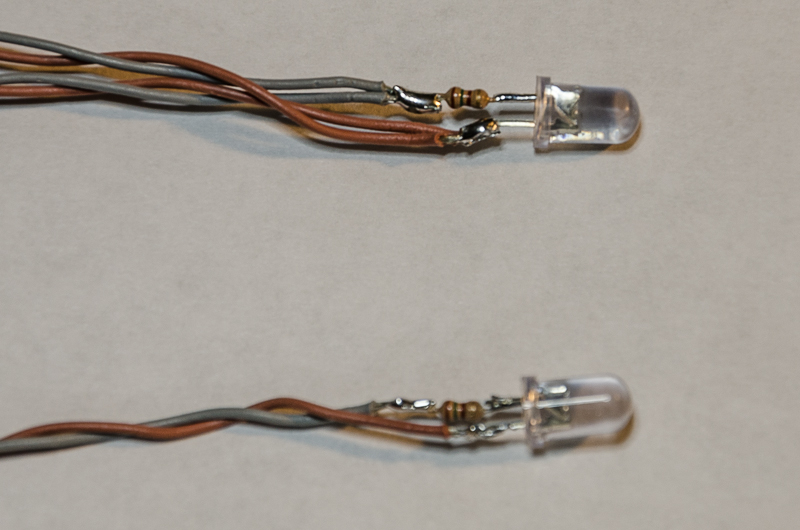
Notice that because of the way the components are placed, even if the leads are pinched together, there won't be a short circuit - at least, it helps to minimize the risk. Better yet would be to place heat shrink over one of the wires but as you will see later, I'm doing it differently.
The wires are cut to length, stripped and twisted together.
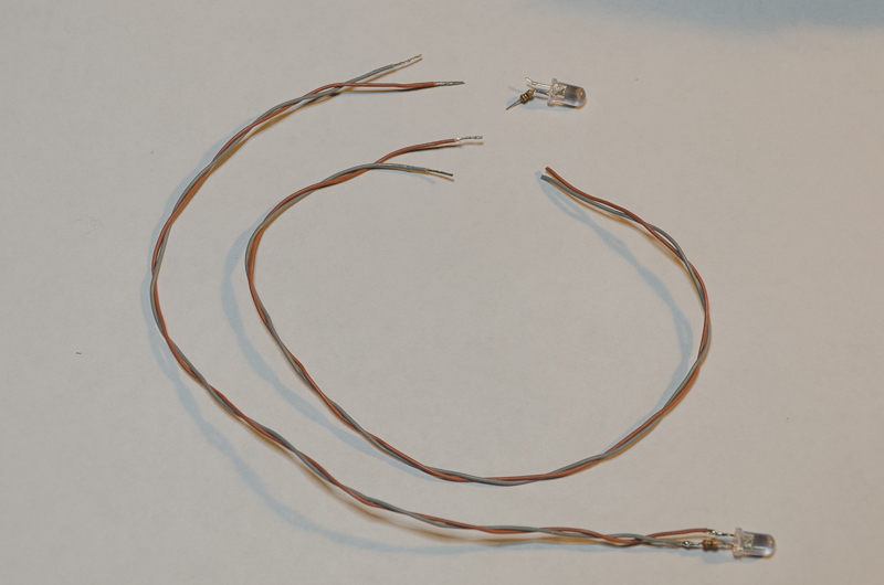
Tin the wires and cut the ends off cleanly.
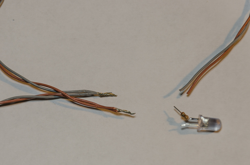
The double wires make things a little bulky, but it will work out.
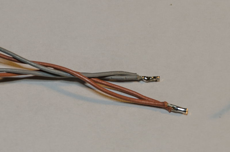
So far, so good.
Make use of the old servo cable.
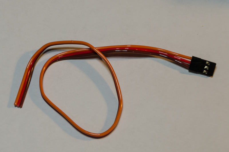
The signal wire in this cable serves no purpose for the LEDs so it gets snipped right next to the plug and then peeled right off.
 Prep the wires for soldering. Remember that grey is negative. Don't forget about heat shrink (yes, I'm using it here). Also note how the wire lengths are staggered to help reduce the chance of shorts.
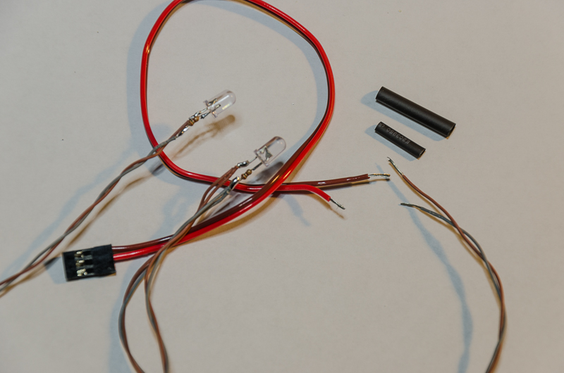
Slide the heat shrink onto the wire before you solder that connection (I still forget to do that sometimes!). In this connection, I have slid the thin heat shrink over the grey wire only and the thick heat shrink is slid over both wires. Slide the thin shrink over the soldered connection and shrink it. Then slide the thicker shrink over both the thin shrink and the other connection.
 Heat shrink is cut to length to cover up the LEDs and resistors. This size of heat shrink won't easily fit over the LED so I stretched it a little wider by sliding it over my pliers and opening it slightly.
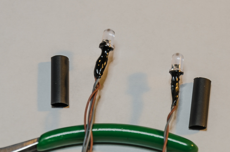
A coat of liquid electrical tape or plasti dip is how I have chosen to insulate around the resistor and LED junction before the heat shrink goes on.
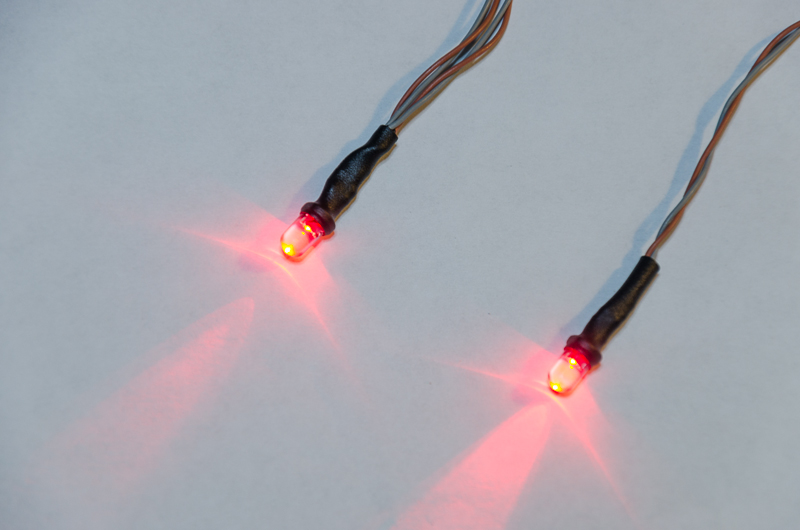
Heat shrink in place and showing off some light!
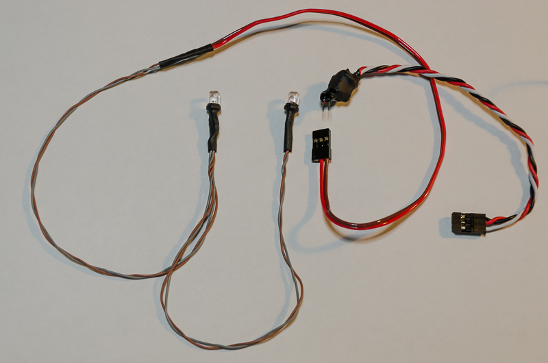
The completed LED string. Shown next to a
https://www.heyokperformance.com/Remote_Switch_for_LED_Lighting/p1742582_8014063.aspxthat could be used to remotely operate the lights.
Happy lighting!
Al


 AED
AED AFN
AFN ALL
ALL AMD
AMD ANG
ANG AOA
AOA ARS
ARS AUD
AUD AWG
AWG AZN
AZN BAM
BAM BBD
BBD BDT
BDT BGN
BGN BHD
BHD BIF
BIF BMD
BMD BND
BND BOB
BOB BRL
BRL BSD
BSD BTN
BTN BWP
BWP BYN
BYN BZD
BZD CAD
CAD CDF
CDF CHF
CHF CLF
CLF CLP
CLP CNH
CNH CNY
CNY COP
COP CRC
CRC CUC
CUC CUP
CUP CVE
CVE CZK
CZK DJF
DJF DKK
DKK DOP
DOP DZD
DZD EGP
EGP ERN
ERN ETB
ETB EUR
EUR FJD
FJD FKP
FKP GBP
GBP GEL
GEL GGP
GGP GHS
GHS GIP
GIP GMD
GMD GNF
GNF GTQ
GTQ GYD
GYD HKD
HKD HNL
HNL HRK
HRK HTG
HTG HUF
HUF IDR
IDR ILS
ILS IMP
IMP INR
INR IQD
IQD IRR
IRR ISK
ISK JEP
JEP JMD
JMD JOD
JOD JPY
JPY KES
KES KGS
KGS KHR
KHR KMF
KMF KPW
KPW KRW
KRW KWD
KWD KYD
KYD KZT
KZT LAK
LAK LBP
LBP LKR
LKR LRD
LRD LSL
LSL LYD
LYD MAD
MAD MDL
MDL MGA
MGA MKD
MKD MMK
MMK MNT
MNT MOP
MOP MRU
MRU MUR
MUR MVR
MVR MWK
MWK MXN
MXN MYR
MYR MZN
MZN NAD
NAD NGN
NGN NIO
NIO NOK
NOK NPR
NPR NZD
NZD OMR
OMR PAB
PAB PEN
PEN PGK
PGK PHP
PHP PKR
PKR PLN
PLN PYG
PYG QAR
QAR RON
RON RSD
RSD RUB
RUB RWF
RWF SAR
SAR SBD
SBD SCR
SCR SDG
SDG SEK
SEK SGD
SGD SHP
SHP SLE
SLE SLL
SLL SOS
SOS SRD
SRD SSP
SSP STD
STD STN
STN SVC
SVC SYP
SYP SZL
SZL THB
THB TJS
TJS TMT
TMT TND
TND TOP
TOP TRY
TRY TTD
TTD TWD
TWD TZS
TZS UAH
UAH UGX
UGX UYU
UYU UZS
UZS VES
VES VND
VND VUV
VUV WST
WST XAF
XAF XCD
XCD XCG
XCG XOF
XOF XPF
XPF YER
YER ZAR
ZAR ZMW
ZMW ZWG
ZWG ZWL
ZWL